DIY Smart Home Automation Using Android 6 Steps Circuit Diagram A relay lies at the heart of this project, acting as an electronic switch that is controlled by an Arduino. As electrical switches, relays open and close based on digital signals received from a computer or microcontroller board. This makes them ideal for DIY home automation, as they work well with Arduinos and other basic boards.
Working of Arduino based Home Automation. Make the connection for Home Automation project as given in the circuit diagram. First of all, we connect the bulb with AC powered sources and with relays as given in the circuit diagram. Then the relays are given DC power from the Arduino Uno board. The circuit is very simple, we just need a Nodemcu board and a relay module to control home appliances securely from the smartphone through the internet. I have shared all the details like esp8266 NodeMCU pinout, circuit, Arduino sketch, Blynk App setup for this smart home project. To build a smart home automation system using Arduino, you will need the following components: Circuit Diagram. Connect the VCC pin of the relay module to the 5V pin on the Arduino board
DIY home automation using Arduino, Relay and Bluetooth Module(HC Circuit Diagram
Relays play an important role in automation circuits. Whether it's industrial or home, the type of relays can change but the principle remains the same. You may already know that relays in home automation are devices that activate another appliance. This might be anything from a light bulb to a motor. Smart home automation can be used in a This is the complete circuit diagram for this home automation project. I have explained the circuit in the tutorial video. The circuit is very simple, I have used the GPIO pins D1, D2, D5 & D6 to control the 4 relays.. And the GPIO pins SD3, D3, D7 & RX connected with push buttons to control the 4 relays manually.. I have used the INPUT_PULLUP function in Arduino IDE instead of using the pull Industrial Automation: Control motors, solenoids, and actuators. Automotive Systems: Manage lighting, sensors, and other high-side loads. Home Automation: Build smart switches for appliances and lighting. Conclusion. The VNI4140K is a versatile and reliable component for building smart power relay systems.

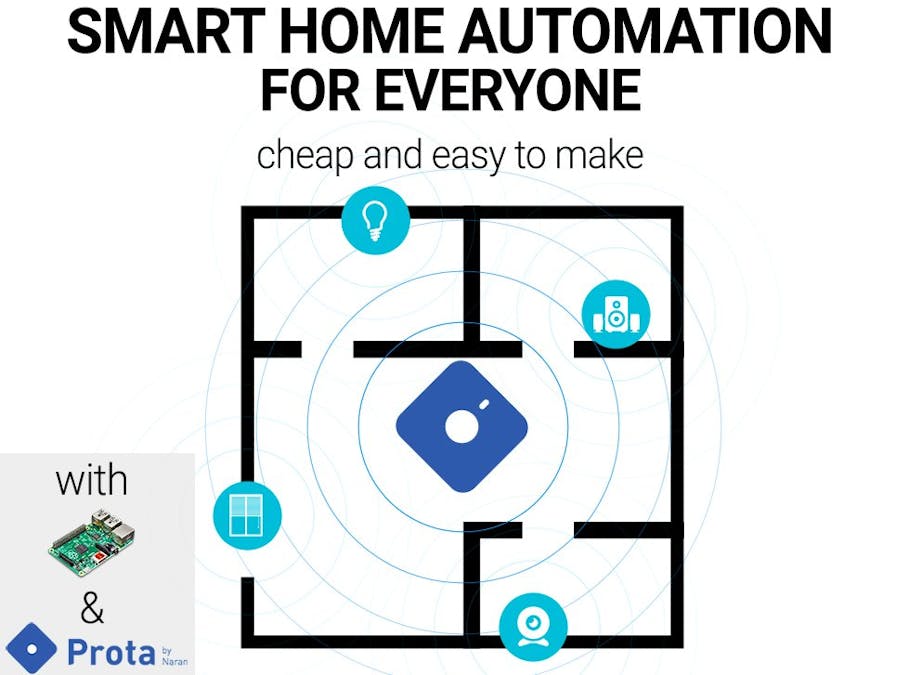
So, in this tutorial we are going to learn about home automation using Arduino, Relay and Bluetooth Module. Here, we have automated our four room appliances namely AC, Bulb, Heater, Fan. Let's get started with the today's tutorial. Components Required: Arduino UNO X 1; 5 Volt Relay Module X 4; HC-05 Bluetooth Module X 1 In this home automation project, we will design a smart home relay module that can control 5 home appliances. This relay module can be controlled from Mobile or smartphone, IR remote or TV remote, Manual switch. This smart relay also can sense the room temperature and sunlight to turn on and off the fan and light bulb. This smart relay has the