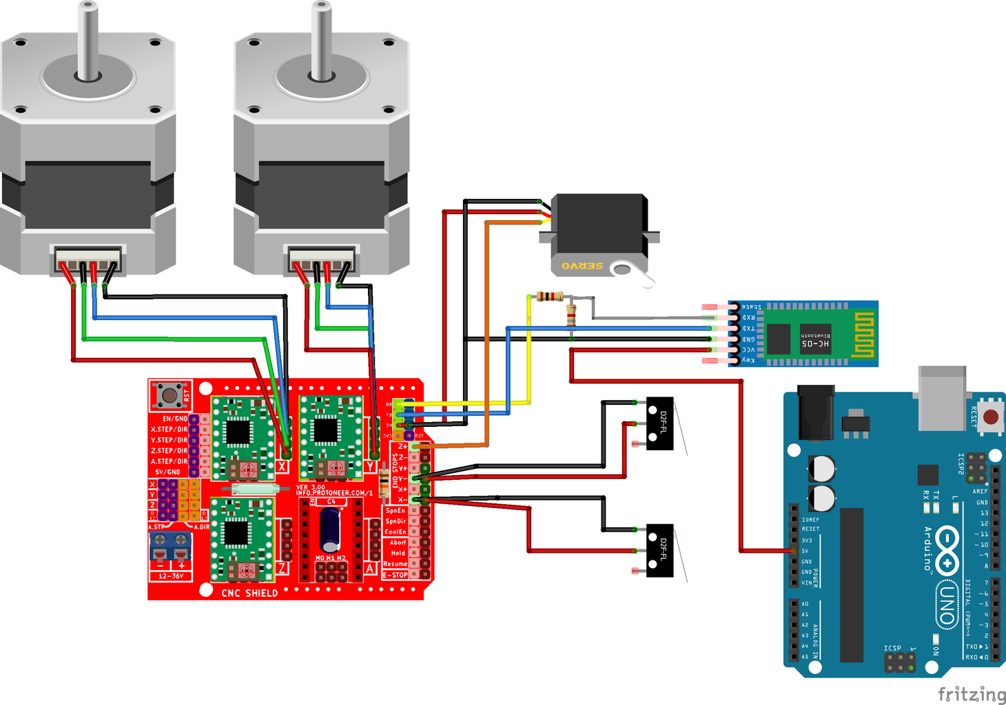
Draw Robot 15 Steps with Pictures Circuit Diagram Explore 75+ DIY robotics projects with detailed circuit diagrams, source code, and complete instructions.Whether you're a beginner or an advanced maker, you'll find exciting projects using Arduino, Raspberry Pi, ESP32, and other microcontrollers.From line-following robots to AI-powered bots, our tutorials make robotics easy to learn and build. SCARA Robot Circuit Diagram. So, we will use an Arduino UNO board in combination with a CNC shield and four A4988 stepper drives. Although it's a robot and it seems more complicated, that's all electronics we need for this project. It's worth noting that, instead of Arduino UNO, we could also use an Arduino MEGA in combination with a
In this tutorial, I'll guide you through producing this enhanced robot with new features like an OLED display, RGB LEDs, and a buzzer for melodies. Follow along as we design the circuit, assemble the PCB, and 3D print the mechanical parts. Let's bring this robot to life with motion control, Bluetooth connectivity, and customizable eye Above, you can see the circuit diagram of this maze-solving robot. It is self-explanatory, as we have provided a clear diagram with all the components marked. For added clarity, I am detailing the circuit below: Since we are using the motor shield v1, we are limited to using the analog pins. Therefore, I am using A0, A1, and A2 as digital
Simple Robot Schematic Diagram Circuit Diagram
Simple robot schematic diagrams are created by connecting the various components such as motors, sensors, and control systems. Control Apparatus And Method For Robot Arm Program Integrated Electronic Circuit Diagram Schematic Image 61. Diy Line Follower Robot Using 8051 Microcontroller With Circuit And Program. Schematic File. teensy_robot.zip. Conclusion. In this article I outlined the requirements for the robot and my design choices to meet those requirements. These choices led to a schematic and bill of materials (BOM) to add up the costs for the project. In part 2 of this series, I'll draw the circuit board so it can be manufactured!

Fortunately, creating a robot with circuit diagram and design isn't as daunting or time-consuming as one might think! To begin, plan out the robot's structure and what you want it to do. This step requires research on the types of materials and parts needed to create a circuit, such as a breadboard, a power source, and various sensors or The receiver and motor driver circuit (Fig. 3) is built around Arduino UNO board (BOARD1), decoder IC HT12D (IC2), 433MHz RF receiver module (RX1), motor driver IC L293D (IC3), regulator IC 7805 (IC4) and a few discrete components. Fig. 1: Block diagram of Arduino based RF controlled robot Fig. 2: Circuit of transmitter section Arduino UNO board
