Electronic Basics 30 Microcontroller Arduino Timers Circuit Diagram Electronics projects based on ATmega32 microcontroller of AVR series. These ATmega32 projects and tutorials are explained with the help of schematics, source codes and videos. In this project we are going to design a simple Alarm clock using ATMEGA32 timers. ATmega32A microcontroller has a 16 bit timer… July 15, 2015. 4x4 Keypad Real-Time Clock (RTC) These are low-resolution timers as compared to General purpose and Systick Timers. They are used to provide time in a human-readable form to the end-user and hence their resolution is usually 1 second. Its basic use is to tell the present time to the end-user, in other words, it acts as a digital watch. In the internal clock mode, Timer0 operates as a timer and uses the internal (FCPU) clock with or without a pre-scaler. The pre-scaler is an integer value that divides the CPU clock to give the Timer Clock, i.e., Timer Clock = FCPU/pre-scaler. When the pre-scaler is set to one or bypassed, the timer runs on the same clock as the CPU is running.
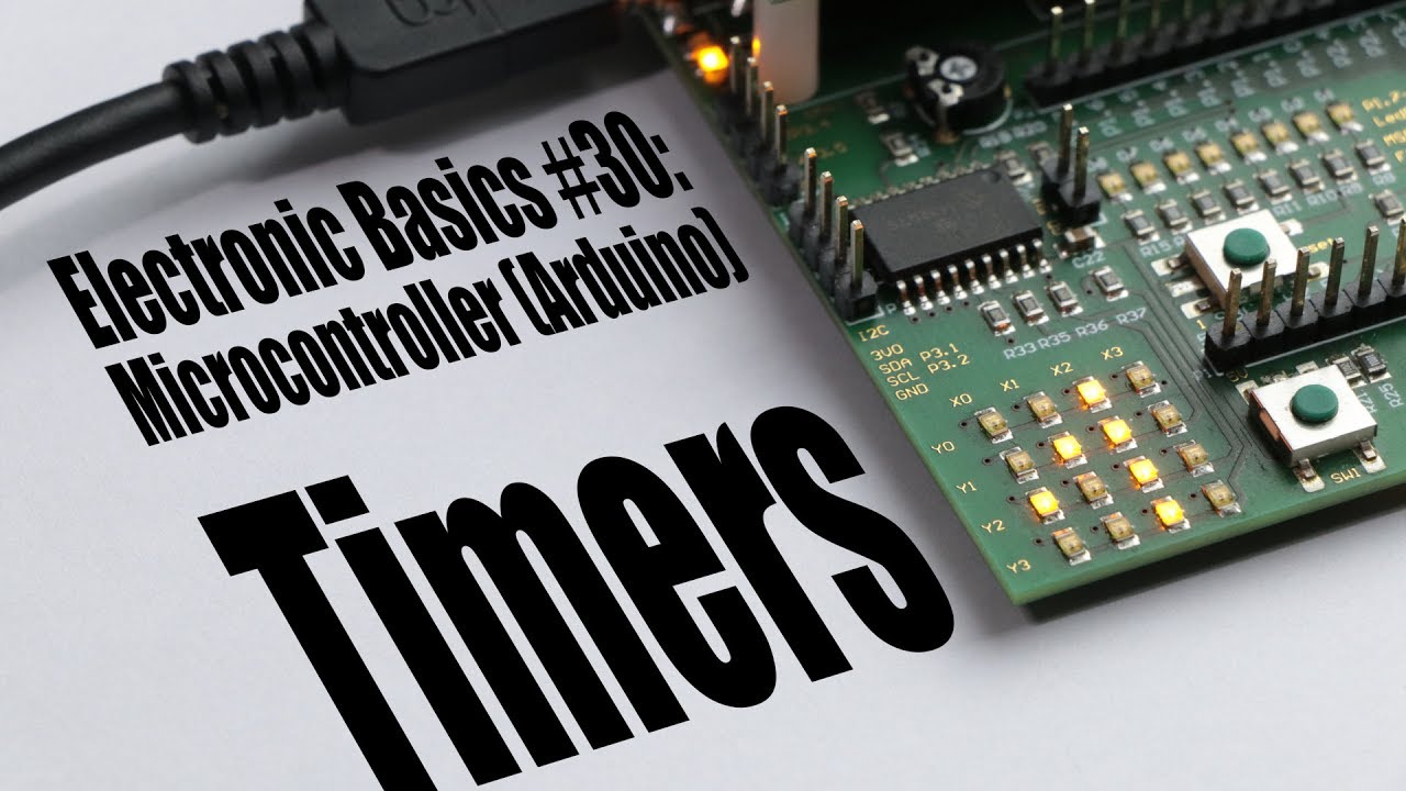
The preloader value of the Timer bit can also be adjusted using pushbuttons to control the duration in which the interrupt occurs. What is TIMER in Embedded Electronics? Timer is kind of interrupt. It is like a simple clock which can measure time interval of an event. Every microcontroller has a clock (oscillator), say in Arduino Uno it is 16Mhz. This microcontroller is used in Arduino which is a popular ready made easy to use microcontroller based system. The microcontroller contain Timers and Counters which are useful for creating time based interrupt, create counting mechanism for counting external events, creating signal waveform, for generating PWM signal for motor controls etc.
8051 Timers and Counters Circuit Diagram
The Arduino-Timer library is a community-contributed library that enables users to configure timer-based events (tasks) without the need to do register-level programming for the timer modules. It uses the built-in timer-based millis and micros functions, so it's like a wrapper layer of useful APIs on top of the built-in timer-based functions. The time it stays HIGH is decided by the size of a resistor and a capacitor. The higher the values, the longer it stays HIGH. If you connect a buzzer to the output, you can create an alarm circuit that is triggered for example by a window being opened. 555 Timer One-Shot Example Circuit. The following circuit turns on an LED when you push the

Specific Design Goals As mentioned already, the primary objective of the first laboratory is to design a digital clock on a 4 LED display using 8-bit 8051 microcontroller. The target system is expected to perform sixty seconds counts, i.e., for example counting from 00:00 to 00:59 in one second interval and repeating the counts one