List 94 Pictures Remote Control Cars Circuit Diagrams Excellent For power supply we are using a old mobile charger with 5V output. Take the charger module out from the case. Connect a wire to input side and out side of charging module.The using a insulation tape insulate the charging module. 2) Precision Infrared (IR) Remote Circuit. The second IR remote control circuit discussed below uses a unique frequency and detects only the specified IR frequency from the given remote transmitter unit, making the design entirely failproof, accurate and reliable. Ordinary IR Remote Drawback 4$ off on first order: https://lcsc.com/Love Components?Save Cost!Good News!Now you can order me to design a custom PCB for you!https://www.fiverr.com/users/
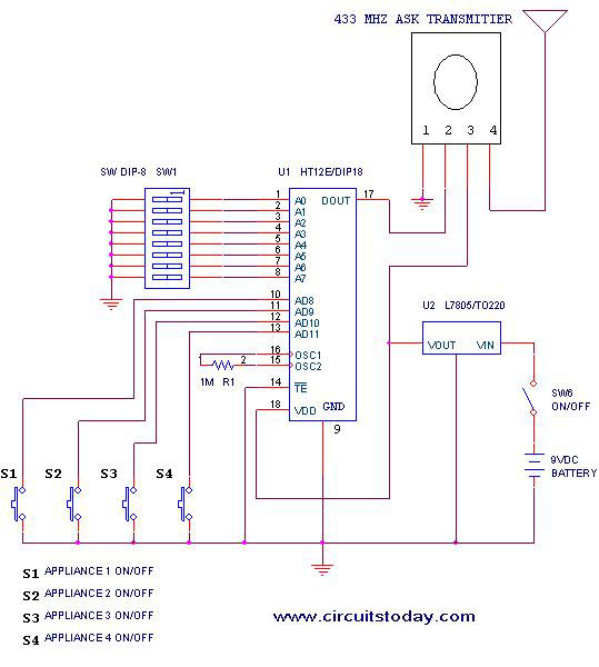
In this video, we are going to show you making a simple remote control switch circuit. Using this circuit you can control your all AC appliance at your home. In this video, I will show you how to build and control an electrical circuit using an inductive sensor and a remote control system. We will explore the nece Making a 433 MHz, 315 MHz RF Remote Control with Relay Flip Flop. Building a hi-end remote control device using very few components today looks pretty plausible. The proposed remote control light switch circuit idea provides you with the opportunity of building and owning this amazing device through simple instructions.
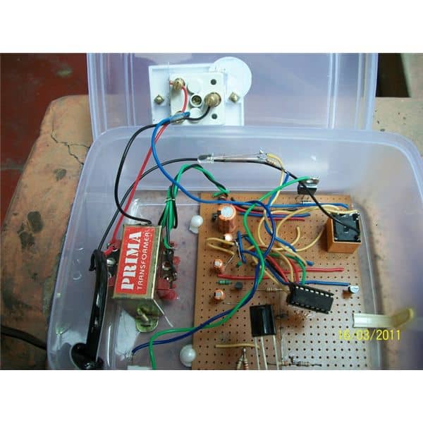
How to Make a Wireless Remote control Circuit at Home Circuit Diagram
Testing the Circuit. Point your IR remote control at the TSOP312 receiver module. Press any button on the remote control. You should see the relay click and its onboard LED will turn ON. Press the button again. The relay should click again, and the LED will turn OFF. Note that this circuit can be a bit sensitive to noise from other IR sources. The BC557 offers similar characteristics to the BC547, making them a perfect match for the remote control switch circuit. Remote Control ON-OFF Switch. Circuit Diagram of Remote Control ON-OFF Switch. This project can be designed using a few basic components. The circuit diagram of this project is shown below.
