SCRs in AC Circuits Circuit Diagram Using a hybrid relay based on both components (relay/Triac), instead of only a relay, have the following benefits: V. MAIN. applied to relay • Relay reliability: The load inrush current is managed by the silicon switch, safely thanks to its high current capability. It also increases the relay lifetime, which only drives the steady-state current.
The above figure shows the use of SCR to switch ON or OFF a.c. power to a load R L.Resistances R 1 and R 2 are for the protection of diodes D 1 and D2 respectively.Resistance R 3 is the gate current limiting resistor.To start the circuit, switch is closed.During the positive half-cycle of a.c. supply, end A is positive and end B is negative contactor, an SCR provides fast response and high resolution as well as the ability to limit current and regulate load voltage, current or power. Disadvantages to using an SCR Power Control can include low power factor, high harmonic currents and radio frequency interference (RFI) when using phase-fired power controllers.

SCR Switch, AC & DC Power Control - Electronics Hub Circuit Diagram
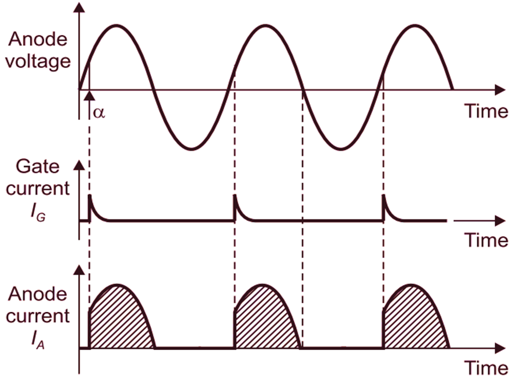
An SCR (silicon controlled rectifier, or thyristor) is a semiconductor switching device, with two power terminals, called the anode (A) and cathode (K) and one control terminal called the gate (G). If terminal K is taken positive with respect to A, the SCR is reverse biased and will block current from flowing.
This method can be effectively used in applications requiring RMS current control or load power control. Battery Charger using SCR. Fence chargers primarily require a high voltage generator stage, where a high switching device like an SCR becomes highly imperative. SCRs thus become specifically suitable for such applications where they are

PDF How to implement an SCR or a Triac in hybrid relay applications ... Circuit Diagram
Zero voltage switching controls proportionally turn on and off each full cycle of the power line. By varying the number of AC power line cycles, the SCR provides power to the heaters. With a variable time base, the optimum number of cycles turned on/off is achieved. This method produces less RFI line noise than phase angle fired SCRs.

However, it is possible to use the TRIAC as a driver for another switching device, as shown in Figure 11. This scheme allows a low-power SSR to control high-current loads by means of external, high-power SCRs. Figure 11 shows how we can use a TRIAC along with three resistors to produce the two controlling signals of Figure 9(B). 425 AMP THREE-PHASE SCR CONTROLLER 1.0 INTRODUCTION TO SCR POWER CONTROL Since the development of SCR power controllers in the late 1950™s, the power handling capabilities of SCR™s (silicon controlled rectifiers) have advanced from a few hundred watts to many megawatts. So, too, the use of SCR power controllers in industrial applications has